Forbidden Advantage
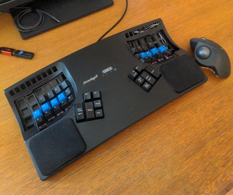
This is a description of my hand-wired Kinesis Advantage 2 [1] running with ZMK [2] and powered by an Elite-Pi board [3] (with a RP2040 ARM microprocessor [4]). I call the result the "Forbidden Advantage".

BUT WHY‽
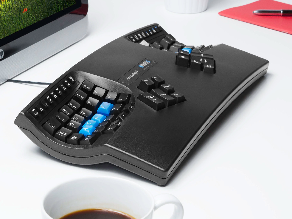
A couple of years ago, I bought the Kinesis Advantage 2 keyboard. However, I never really got used to it and it landed in a box. What a waste of money! The following are the major problems I was facing with my Kinesis Advantage 2.
- The spring-ping of the Cherry MX Brown switches was unbearable. The big, hollow plastic case makes this even worse as it resonates.
- Although the keys are positioned better than on a traditional keyboard, I still had to move my hands to reach some of them.
- The proprietary firmware is rather limiting and (to my knowledge) doesn't support more than 2 layers.

SOLUTION
Keep the case and some of the circuit boards and replace everything else ¯\(ツ)/¯. Damien Rajon did something very similar [5]. The difference is that he kept all the keys (except the F-key rows). An alternative solution to use a different controller would have been to use a custom PCB such as the kinT kinesis keyboard controller made by Michael Stapelberg [6]. I decided against this solution because I would still have had to use the original PCBs for the keys in the keywells.
There are two major open source firmwares intended for keyboards: QMK [7] and ZMK [2]. Both of them provide all the features I require. I decided to go with ZMK because the configuration looks much cleaner and I like the way you can build the firmware in a github action (using docker).
I acquired the following bits and pieces:
- The Elite-Pi is a tiny board featuring the new RP2040 ARM microcontroller (ZMK does not yet officially support it but there es a pull-request from the ZMK author [8] - Good enough)
- Gazzew Bobagum silent linear switches
- Kailh Hot-Swap sockets (such that I can easily swap the switches if I don't like them)
- 1N4148 THT Diodes.
- Wires (I sacrificed an old ethernet cable).
- A USB cable.
PROTOTYPE
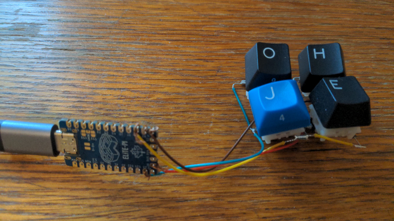
Before I started soldering the real keyboard with 40 keys, I wanted to create a prototype to ensure everything works as expected. So I soldered together four hot-swap sockets, put switches on them and configured the firmware [9]. Ohje, what have I signed myself up for‽

LET'S GO
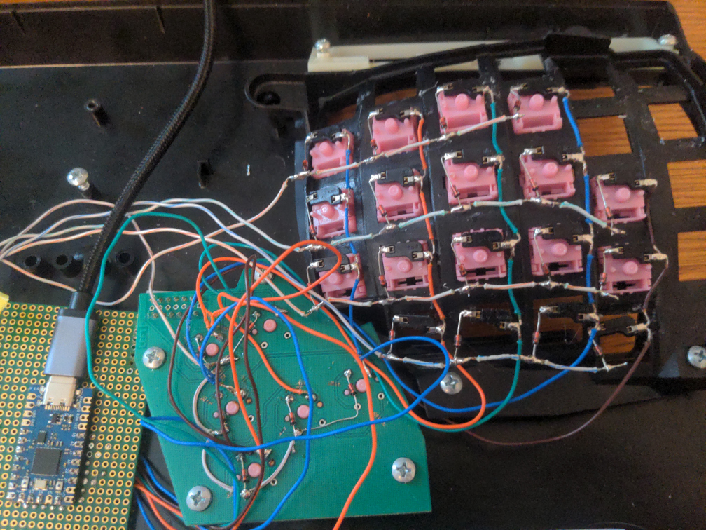
I will not lie. Soldering all the hot-swap sockets and diodes took way longer than I expcected. As you can see in the following image of the left-hand side of the keyboard, I added some additional sockets at places where there are no switches just in case I later decide I need more keys. I didn't bother reverse-engineering the PCBs for the thumbclusters and just destroyed the lanes and rewired them. And yes, I totally forgot to buy Mill-Max sockets to make them hot-swappable. I removed the PCBs for the keys in the concave keywells as it was thin and flexible and I don't think putting the Kailh hot-swap sockets on them would have been wise.

The switches are organized in a grid with 5 rows and 12 columns which are connected to the microcontroller. The following image shows which key is in which row and column. The grey keys are the ones without a switch.
KEYMAP
This is a very difficult decision. There are tons of different layouts to choose from. I decided to go with a colemak-dh [10] variant and took much inspiration from Callum Oakley's layout [11].
The default layer contains most letters. By pressing "w" and "f" at the same time produces a "q". I also have some keys for debugging on the thumb cluster. This allows me to debug with one hand and scratch my head with the other.
The symbols layer is active when the "SYM" key is held down. The grey keys on the right home row are "sticky", meaning they can be released to type combinations such as "Ctrl-C".
The navigation layer is active when the "NAV" key is held down.
The numbers layer is active when both the "SYM" and "NAV" keys are held down.
REGRETS
- I forgot to buy Mill-Max sockets for the thumbclusters. The switches are soldered directly onto the PCB and are therefore not hot-swappable.
- Using the prototype board instead of ditectly soldering the cables onto the controller was a mistake. It cost me a lot of nerves and I didn't really gain anything. A board with lanes would probably have easier too.
RESOURCES
- Forbidden Advantage ZMK config
- kinT kinesis keyboard controller (by Michael Stapelberg)
- Handwiring a Kinesis Advantage keyboard (by Damien Rajon)
- Callum's layout
- AlaaSaadAbdo's config
- rafaelromao keymap